Floor plan
[edit] 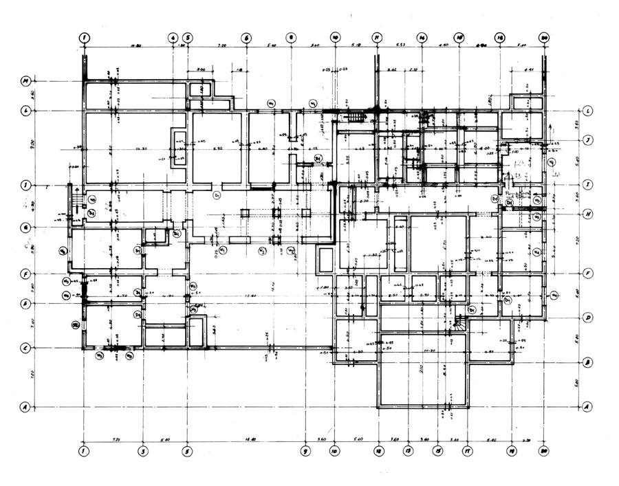
Orthographic projection is a technique for drawing a three dimensional object in two dimensions, by ‘projecting’ its surfaces into a two dimensional representation, where the projection lines are orthogonal to (perpendicular to) the projection plane (that is, there is no foreshortening or perspective).
Floor plans are a form of orthographic projection that can be used to show the layout of rooms within buildings, as seen from above. They may be prepared as part of the design process, or to provide instructions for construction, often associated with other drawings, schedules, and specifications.
Floor plans may include key dimensions and levels, and may also use, hatching, symbols and other standard annotations and abbreviations to indicate materials, fittings and appliances, and so on.
Depending on the size of the building, floor plans are typically drawn at scales of between 1:200 and 1:20. Different line types, colours and weights can be used to differentiate between the types of drawn information they include.
Floor plans can be drawn for whole buildings, a single floor of a building, or just a single room. The more detailed the floor plan is in terms of layout, fittings and so on, the more useful and instructive it will be for the project. However, if spaces are complex, it is normal for separate drawings to be prepared for different trades, such as electrical and lighting drawings, plumbing drawings, and so on.
The lower-right-hand corner of the sheet is typically reserved for a title block. This provides a space to record the name of the project, the name of the drawing, the scale, the originators name, the date, revision history, and so on.
The floor plan view should be roughly centred on the sheet, with the front of the building typically drawn along the lower side of the sheet. A north point may be included to show the orientation of the floor plan.
Typically, the outside walls are drawn first, to lay the plan out on the sheet, then the internal walls, then windows, doors, stairs, lifts, ramps, and so on, are added. An arrow is used to indicate the upward direction of stairs and ramps. It is usual for a faint dotted line to be drawn around stairs (or other openings) where they are open at ceiling level.
Rooms should be clearly labelled, with block lettering in the centre of each room. The correct symbols should be added for elements such as; appliances, fixed furniture, fittings, building services, and so on.
Electrical symbols should be added to the drawing, indicating; power sockets, light switches, wall and ceiling lights, detectors and alarms, extract fans, and so on.
Items that are ceiling mounted, are generally drawn on the floor below their place of installation.
Dimension may be added to indicate the size and location of key elements such as; rooms, fittings, appliances or fixtures, external walls, window and door openings, and so on.
Section lines may be added where there are section drawings associated with the floor plan. Grid references may also be added to help co-ordinate the floor plan with other drawings.
Some floor plans may include notional furniture to help gauge the likely size of circulation spaces.
If a window or door schedule is to be prepared, doors and windows may be labelled with a number or letter, corresponding to an item on the schedule.
Floor plans should not duplicate information that is presented in specifications or schedules because of the potential for conflict. Instead they should refer to the specification or schedule.
[edit] Related articles on Designing Buildings Wiki
- Block plan.
- Common mistakes on building drawings.
- Decorating a newly built home.
- Drawing projections.
- Electrical drawing.
- Elevations.
- General arrangement drawing.
- Manual drafting techniques.
- Residential design and 3D rendering.
- Section drawing.
- Standard hatching styles for drawings.
- Symbols on architectural drawings.
- Techniques for drawing buildings.
- Types of drawings.
- Working drawing.
Featured articles and news
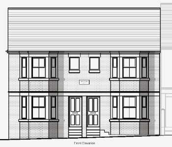
A case study and a warning to would-be developers
Creating four dwellings for people to come home to... after half a century of doing this job, why, oh why, is it so difficult?
Reform of the fire engineering profession
Fire Engineers Advisory Panel: Authoritative Statement, reactions and next steps.
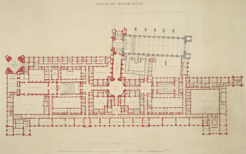
Restoration and renewal of the Palace of Westminster
A complex project of cultural significance from full decant to EMI, opportunities and a potential a way forward.
Apprenticeships and the responsibility we share
Perspectives from the CIOB President as National Apprentice Week comes to a close.
The first line of defence against rain, wind and snow.
Building Safety recap January, 2026
What we missed at the end of last year, and at the start of this...
National Apprenticeship Week 2026, 9-15 Feb
Shining a light on the positive impacts for businesses, their apprentices and the wider economy alike.
Applications and benefits of acoustic flooring
From commercial to retail.
From solid to sprung and ribbed to raised.
Strengthening industry collaboration in Hong Kong
Hong Kong Institute of Construction and The Chartered Institute of Building sign Memorandum of Understanding.
A detailed description from the experts at Cornish Lime.
IHBC planning for growth with corporate plan development
Grow with the Institute by volunteering and CP25 consultation.
Connecting ambition and action for designers and specifiers.
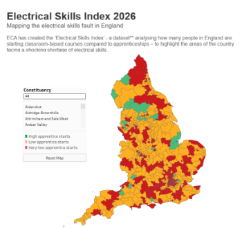
Electrical skills gap deepens as apprenticeship starts fall despite surging demand says ECA.
Built environment bodies deepen joint action on EDI
B.E.Inclusive initiative agree next phase of joint equity, diversity and inclusion (EDI) action plan.
Recognising culture as key to sustainable economic growth
Creative UK Provocation paper: Culture as Growth Infrastructure.
Futurebuild and UK Construction Week London Unite
Creating the UK’s Built Environment Super Event and over 25 other key partnerships.
Welsh and Scottish 2026 elections
Manifestos for the built environment for upcoming same May day elections.
Advancing BIM education with a competency framework
“We don’t need people who can just draw in 3D. We need people who can think in data.”


